Product classification:Positive design of vacuum equipment
Application examples of using straight tube filtering arc to prepare diamond-like carbon films and changing magnetic field distribution and blocking structure on the influence of large particle parameters
In the experiment, the arc source magnetic field is divided into two parts: the magnetic field of the permanent magnet at the back of the target material and the magnetic field of the electromagnetic coil outside the tube wall. The permanent magnet at the back of the target material is a ring-shaped permanent magnet. Considering only the magnetic field of the permanent magnet, the inner diameter of the magnetic ring has a greater impact on the vertical magnetic field of the target surface. The larger the inner diameter of the magnetic ring, the smaller the difference in the vertical magnetic field of the target surface; The outer diameter of the magnetic ring has a relatively small impact on the vertical magnetic field, while the thickness of the magnetic ring has a relatively minimal impact on the strength of the vertical magnetic field. The increase in thickness of the permanent magnet on the target surface results in a decreasing effect. When the thickness and width of the permanent magnet ring are constant, the larger the inner diameter of the permanent magnet ring, the greater the horizontal magnetic field on the target surface, and the smaller the difference in vertical magnetic field.
In the experiment, the permanent magnet model is N35, with an outer diameter of 40 mm, an inner diameter of 20 mm, and a thickness of 10 mm. The coil magnetic field is opposite to the magnetic field generated by the permanent magnetic ring on the target surface. After installing the permanent magnet, it couples with the coil magnetic field on the target surface to form an arched magnetic field. The experiment changes the magnetic field under fixed bias voltage, duty cycle, and deposition time conditions, and sets independent variables based on the presence or absence of blocking structures.
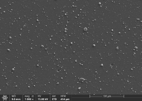
Figure 3 shows the surface and cross-sectional morphology of the prepared diamond-like carbon film; Figures 4 and 5 are line graphs showing the changes in the number and average size of large particles. As shown in the figure, the number of large particles has different trends under different magnetic field conditions. In the case of setting a permanent magnet, both curves of the number of large particles show a slight upward trend with the increase of coil current. When there is a permanent magnet and the coil current is greater than 1A, as the coil current increases, the horizontal magnetic field on the target surface gradually increases, and the zero point of the magnetic field moves towards the center of the target surface. The horizontal magnetic field strength at the axis of the target surface is zero, and the maximum value appears at the edge. The magnetic field distribution is shown in Figure 2. In the presence of permanent magnets, as the coil current increases, the arc spot tends to move closer to the axis of the target surface. Due to the tendency of large particles to move in small angle directions with the target surface, and the high focusing degree of the ion beam emitted by the graphite target, an increase in magnetic field strength will improve the focusing degree, reduce the expansion degree of the cathode plasma, increase the impedance of the plasma, and increase the arc spot emission power. This change will also affect the emission of large particles. In summary, the increase in the number of large particles is due to two reasons: firstly, the movement of the arc spot towards the center increases the probability of large particles escaping; secondly, the increase in arc spot power increases the number of large particles emitted.
From the distribution curve of the average size of large particles, it can be seen that the size of large particles tends to decrease with the increase of coil current. This phenomenon is related to the horizontal component of the coil magnetic field on the target surface. In the experiment, the horizontal component of the coil magnetic field on the target surface is related to the size of the coil current. The larger the coil current, the greater the horizontal component of the coil magnetic field on the target surface. The speed of the arc spot movement on the target surface is positively correlated with the strength of the horizontal magnetic field on the target surface. Therefore, the increase of coil current accelerates the movement of the arc spot, and the speed of the arc spot movement increases, thereby reducing the average size of the emitted large particles.
When there is only a coil magnetic field, the curve of the number of large particles shows a trend of first decreasing and then increasing. Under this condition, the axial magnetic field strength inside the target surface and arc source is relatively high, and the coil magnetic field has a certain horizontal component at the edge of the target material. At this time, the arc spot tends to move more at the edge of the target material. The average size curve of large particles shows a trend of first increasing and then decreasing. Under the condition of a coil current of 2.0 A, there is a situation where the number of large particles is small and the size is large. Due to the fact that the magnetic field strength used in the experiment can only magnetize electrons, and the mass of large particles does not decrease during flight, the change of large particles is mainly determined by the large particles emitted by the arc spot. The faster the speed of the arc spot movement, the smaller the average size of the large particles emitted. Under this condition, in the presence of only an electromagnetic field, the speed of the arc spot movement first decreases and then increases. At the same time, the increase in arc spot power correspondingly increases the number of large particles emitted after 2.0 A.
Comparing the curves of the number of large particles with and without permanent magnets, it can be seen that the number of large particles in the thin film with permanent magnets is greater than that with only electromagnetic fields. This phenomenon may be due to the arch shaped magnetic field formed by the high-level component of the composite magnetic field, which causes the arc spot to approach the axis of the target material and increases the number of large particles emitted. Comparing the average size distribution of large particles under two different magnetic fields, it can be seen that when the coil current is 1.5 A, only the large particle size of the electromagnetic field experimental group is smaller than that of the permanent magnet plus electromagnetic group. Under the condition of composite magnetic field, the permanent magnet magnetic field plays a dominant role on the surface of the target material, and in this case, the speed of arc spot movement in the composite magnetic field is lower than that of the pure electromagnetic field. When the coil current is 2.0 A, only the large particle size of the electromagnetic field experimental group becomes larger than that of the permanent magnet plus electromagnetic experimental group. Within this range, the composite magnetic field arc spot movement speed increases with the increase of coil current, which leads to the reduction of large particles. When the coil current is 2.5 A, it can be seen that the average size of large particles under the composite magnetic field condition has a further decreasing trend. Under unobstructed conditions, the average size of the composite magnetic field is still lower than that of the pure electromagnetic field. The presence of permanent magnets changes the overall trend of changes in the number and average size of large particles, indicating that the presence of permanent magnets has a significant impact on the motion of arc spots and the emission of large particles.
Figure 6 shows that under the same magnetic field conditions, setting up a blocking structure significantly reduces the number of large particles on the surface of the film. The experimental group with a blocking structure has 60% to 70% of the number of large particles in the experimental group without a blocking structure, proving that the blocking structure set on the inner wall of the pipeline has an effective filtering effect on large particles. From the average size curve of large particles, it can be seen that the experimental group with a blocking structure has a larger average size of large particles than the experimental group without a blocking structure. A decrease in the number of large particles but an increase in average size means that the filtering structure filters out more smaller particles. One reason is that larger particles have a stronger escape effect when facing the blocking structure, and a larger size means that they have higher kinetic energy and are more likely to rebound and escape from the filtering area when facing the blocking structure; Another factor is that large particles emitted near the axis during the generation and emission process have a larger average size and are more likely to escape from the filtering area, while large particles emitted at a large angle to the target surface have a smaller average size and are more easily captured by blocking structures.
Preparation of diamond-like carbon films using straight tube filtering arc and the effect of changing magnetic field distribution on sp3 bond content in diamond-like carbon films
Figure 7 shows the line graph of the changes in ID/IG values and sp3 bond content. When a permanent magnet is placed behind the target material, Raman spectroscopy data shows that the ID/IG values of the film decrease with the increase of electromagnetic coil current, while the bond content curve in XPS data increases with the increase of coil current. The same phenomenon also occurs in the experimental group without permanent magnet. Comparing the bond content curves with and without permanent magnet, it can be seen that the experimental group with permanent magnet has higher bond content than the experimental group without permanent magnet under the same coil current.
This law is related to the motion of plasma in a magnetic field. In the experiment, the coil current generates an axial magnetic field on and in front of the target surface, which hinders the movement of charged particles perpendicular to the magnetic field lines. In the experiment, it can be observed that the plasma emitted by the arc spot forms a cylindrical beam. The expansion of plasma is relatively reduced compared to the absence of an axial magnetic field, and the decay rate of charged particle interactions is correspondingly slower. In the presence of a magnetic field, it can be observed that ions have higher charge states. The relationship between magnetic field strength and average ion charge state is shown in Figure 8.
The magnetization of electrons in a magnetic field has a direct impact on the increase of ion charge states. When the magnetic field strength is too high, the ion charge state tends to stabilize and does not further increase. Before a magnetic field strength of 1 T, the ion charge state has a significant increase. The average strength of the magnetic field generated by the coil current in the experiment is 11.75~23.63 mT, much lower than 1 T. It is located in the region where the ion charge state increases with the increase of magnetic field strength. The coil current is positively correlated with the magnetic field strength generated by the electromagnetic coil, that is, increasing the coil current will to some extent improve the ion charge state in the arc plasma.
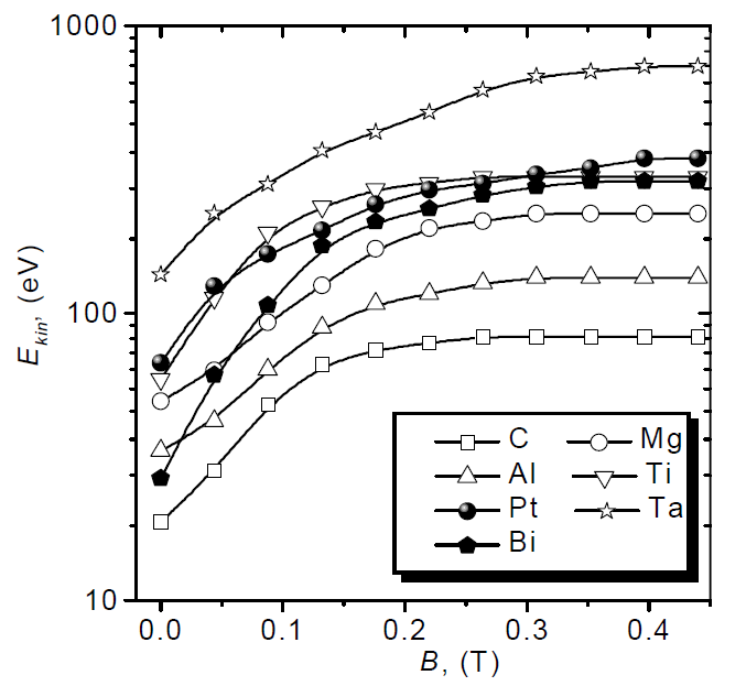
The magnetic field also affects the kinetic energy of ions, and the strength and distribution of the magnetic field are both factors that affect the kinetic energy of ions. Firstly, there is the influence of absolute magnetic field strength. The presence of a magnetic field hinders the movement of electrons perpendicular to the magnetic field lines, resulting in an increase in plasma impedance. That is, under the same arc current, the arc spot requires a higher voltage to generate and maintain the discharge process. The increase in arc spot combustion voltage means that the arc spot has greater input power, higher electron temperature, and higher pressure gradient, ultimately resulting in greater ion velocity. At the same time, the increase in ion charge state is approximately proportional to the increase in arc spot input power. Figure 9 shows the relationship between ion kinetic energy and magnetic field strength.
In the experiment, increasing the coil current further enhanced the axial magnetic field in the arc source space. The charge state and ion kinetic energy of carbon ions increased with the increase of the magnetic field, and the increase in charge state and energy promoted the generation of thin film bonds. In the experimental group with permanent magnets, the permanent magnets generated larger axial and normal magnetic field components on the surface of the target material. The increase in magnetic field strength further altered the charge state and kinetic energy of carbon ions, resulting in a higher bond content compared to the experimental group without permanent magnets.
Figure 1
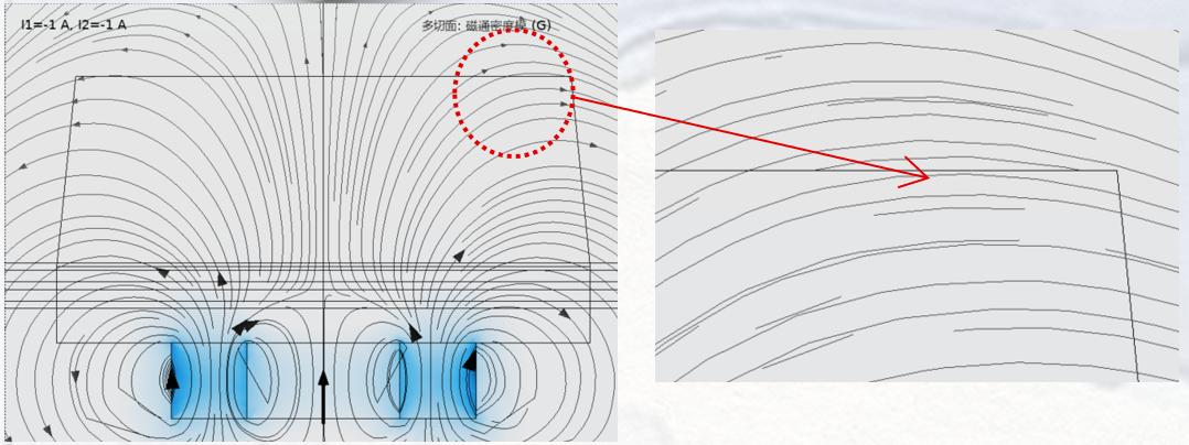
(a) Coil current 1.0 A
Figure 2
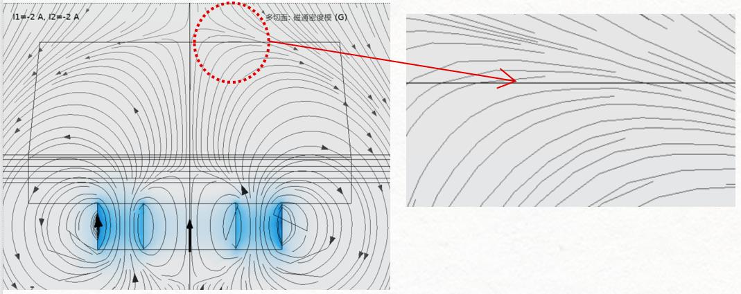
(b) Coil current 2.0 A
Figure 3
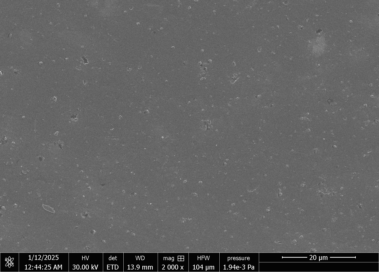
(a) Surface morphology of DLC film prepared by straight tube filtration arc
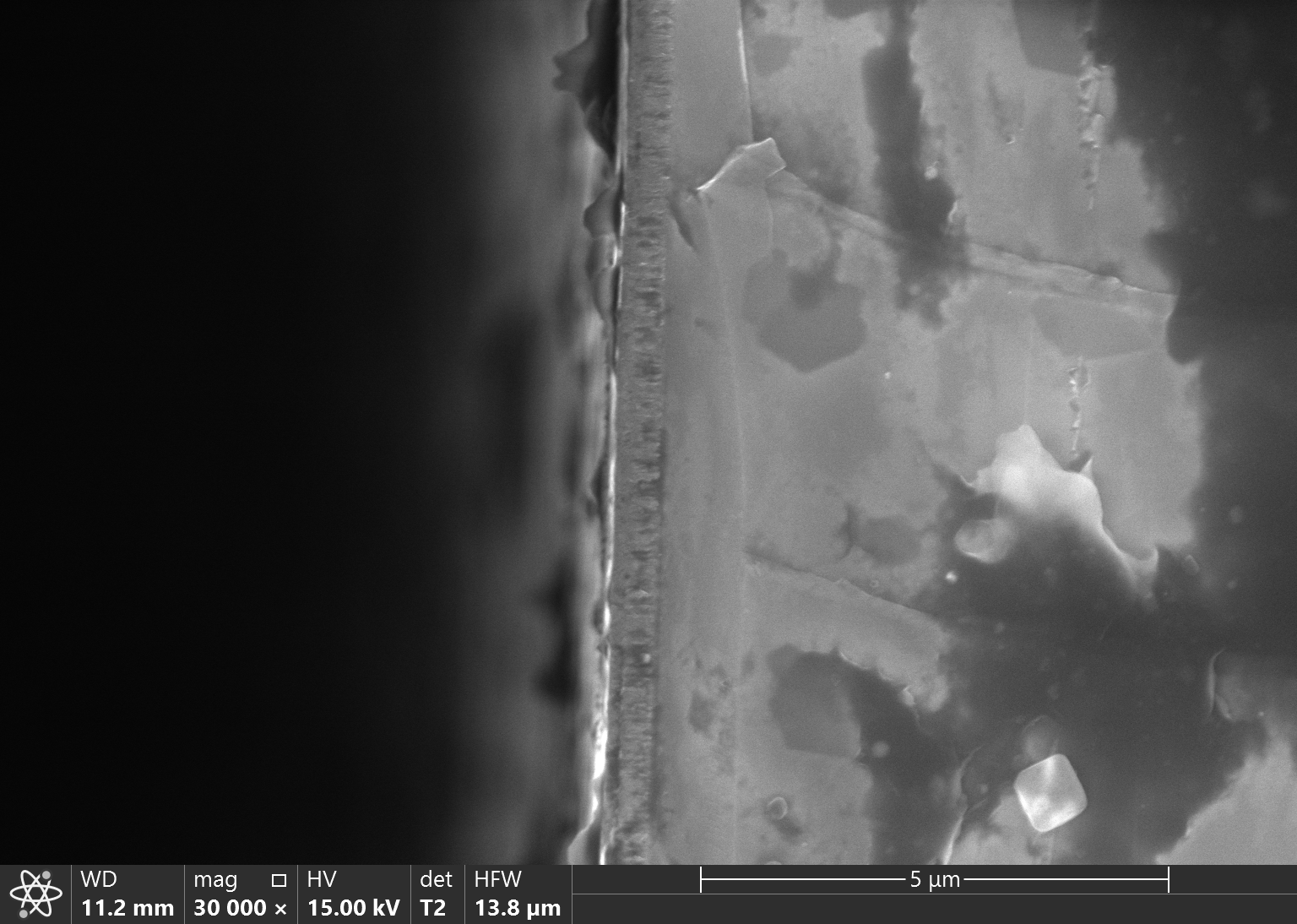
(b) Cross sectional morphology of DLC film prepared by straight tube filtration arc
Figure 4
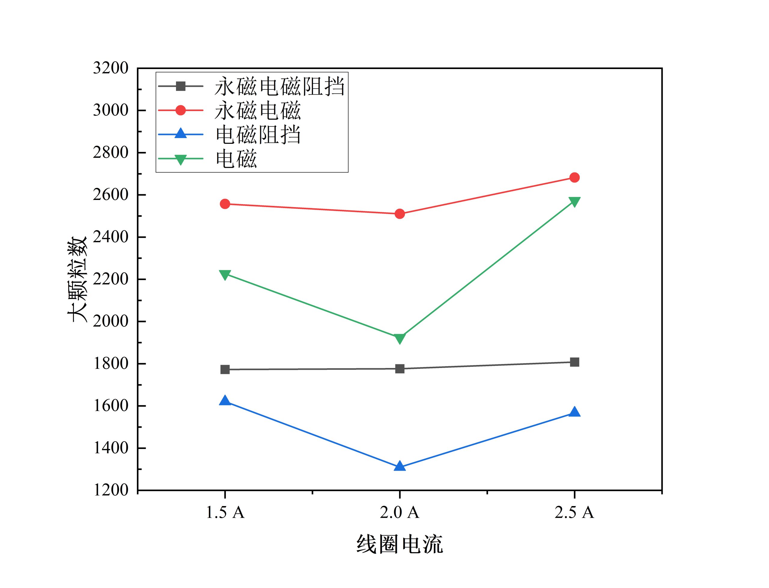
Figure 5
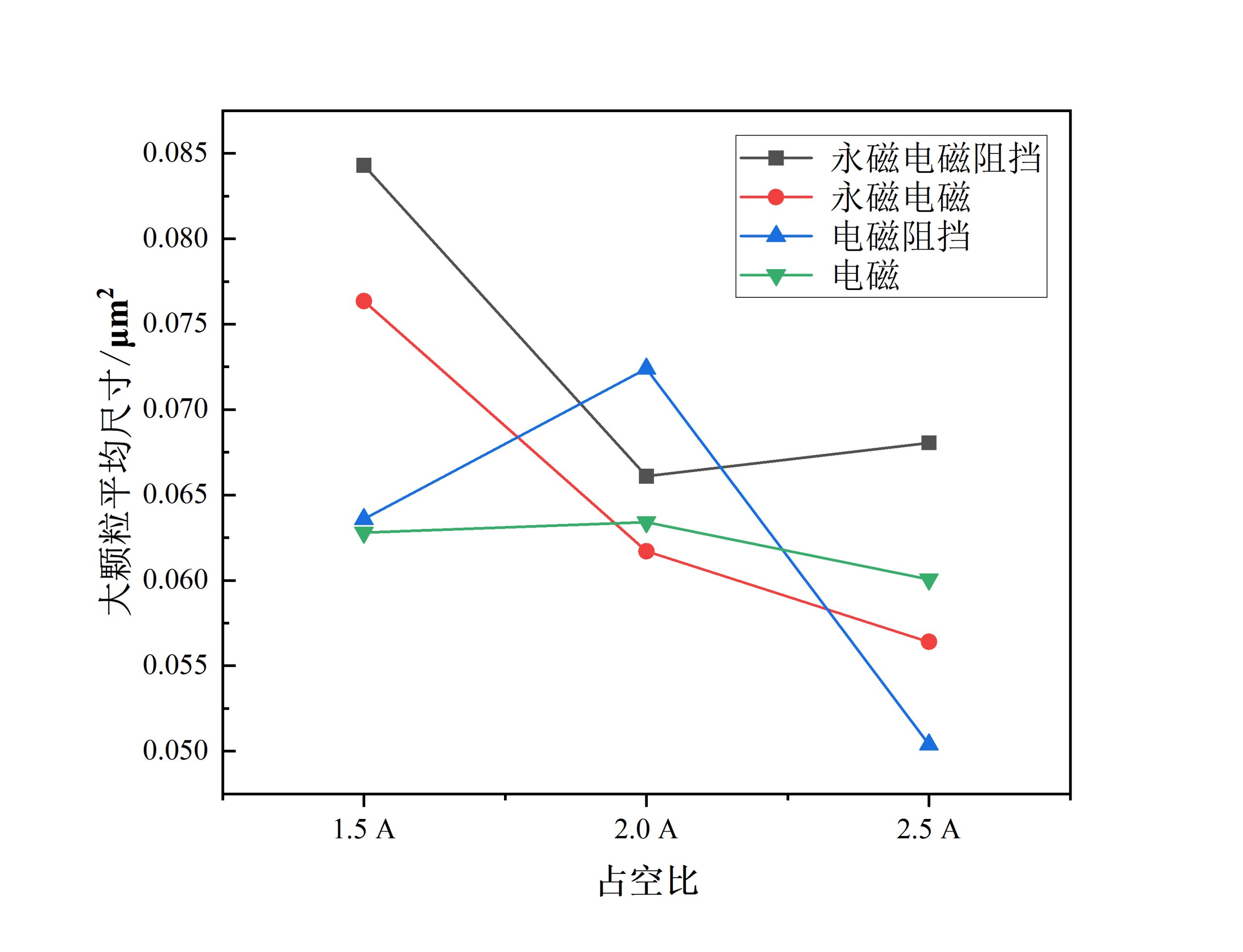
Figure 6
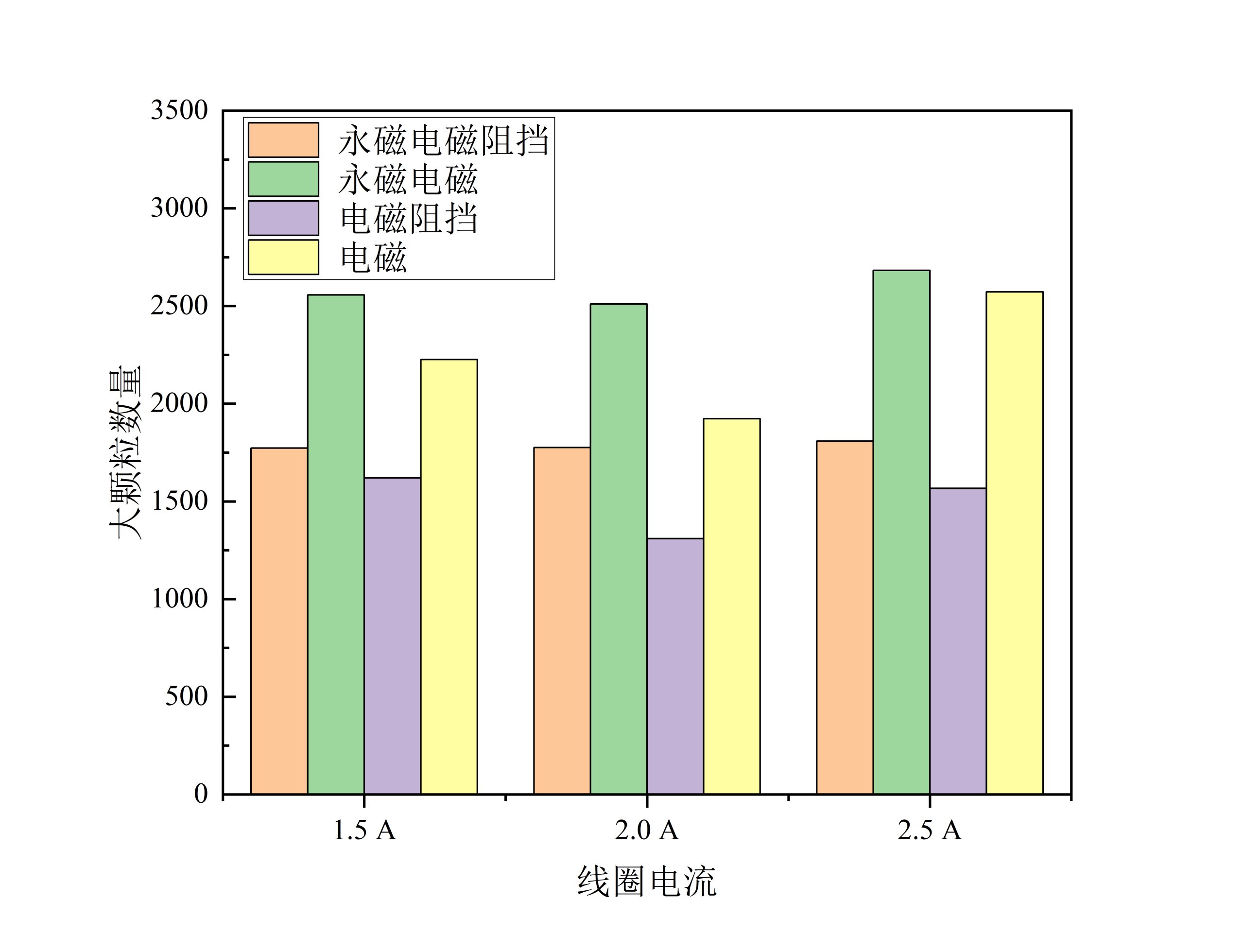
Figure 7
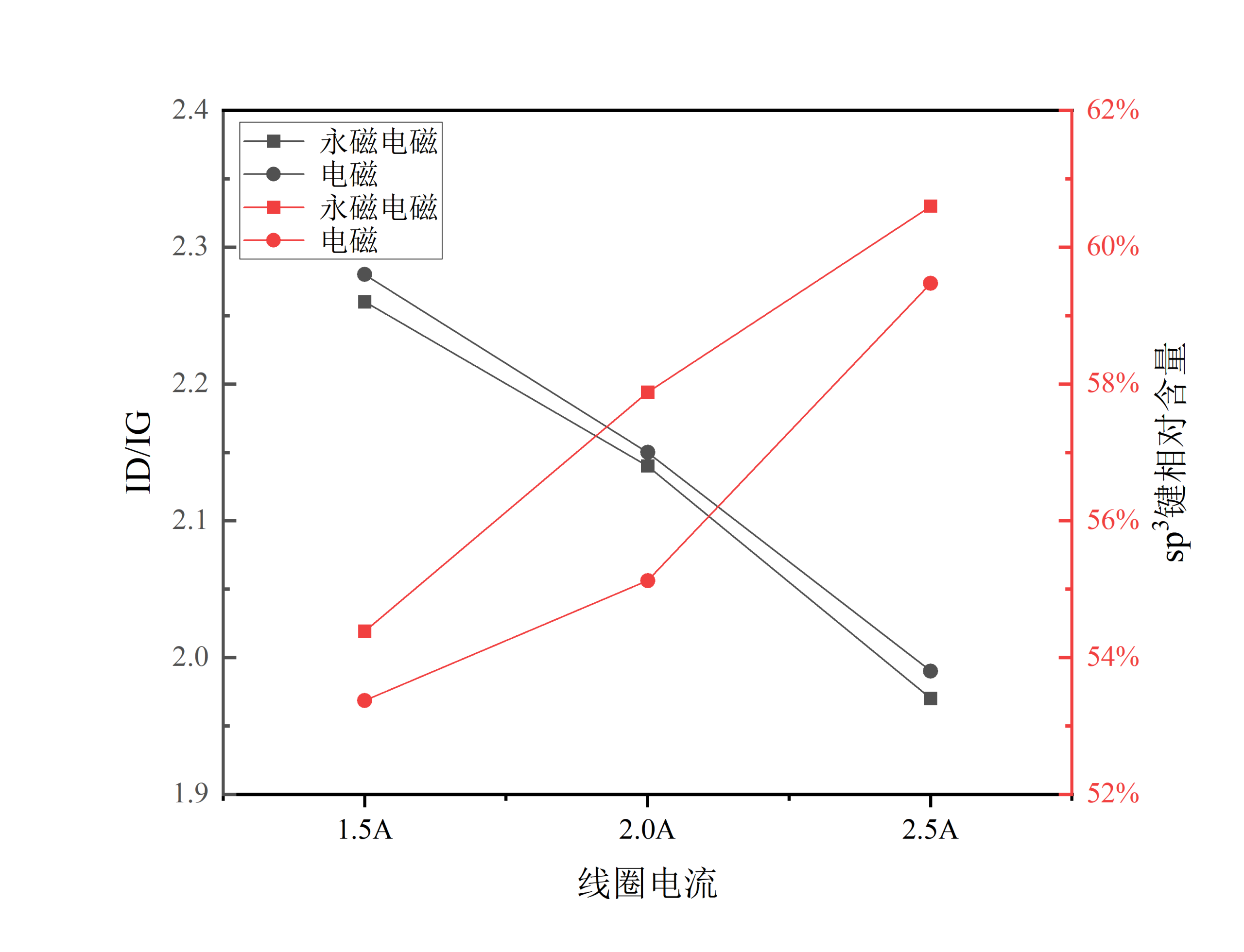
Figure 8
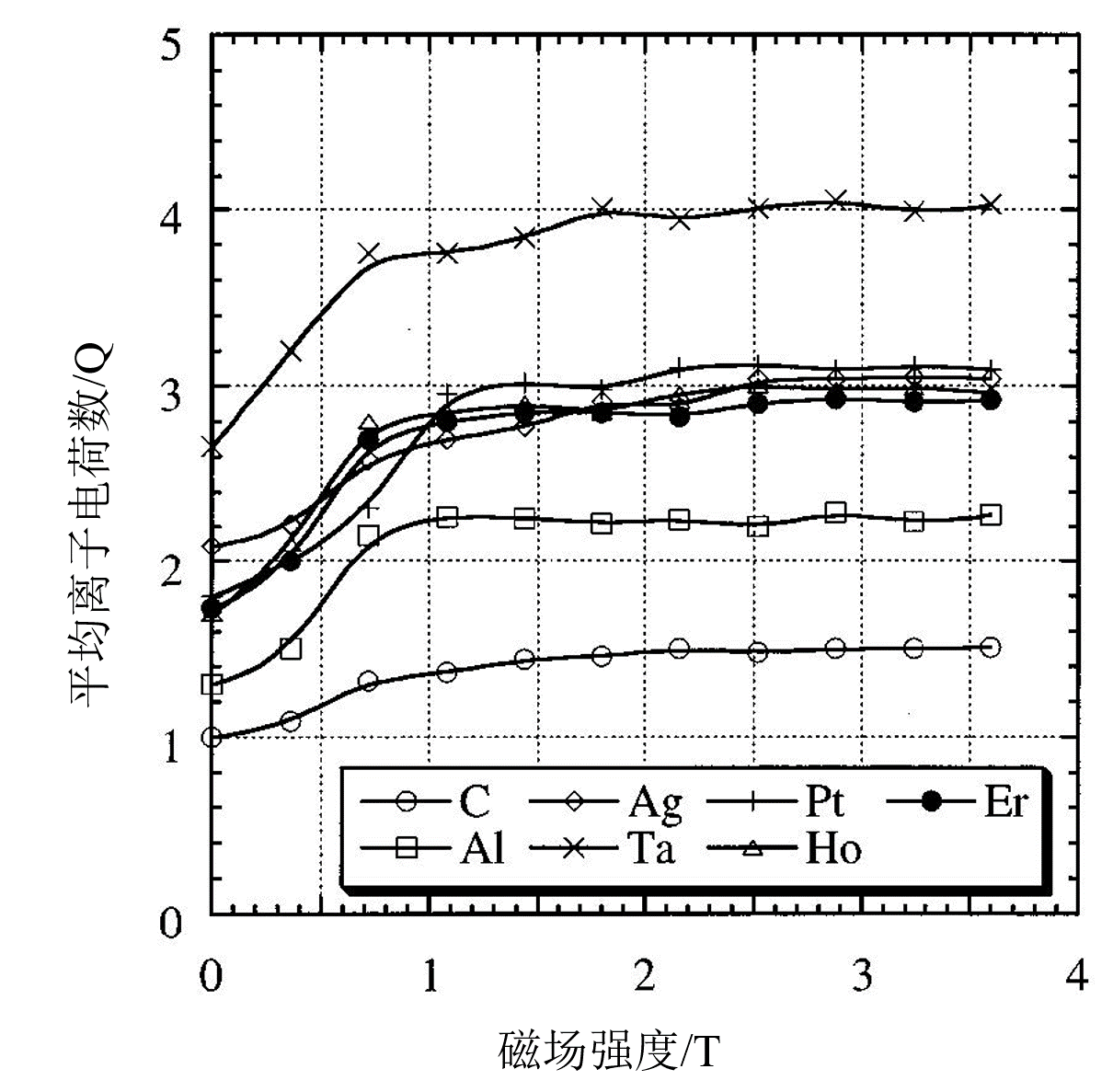
Figure 9
Preparation of TIN film using straight tube filtration arc
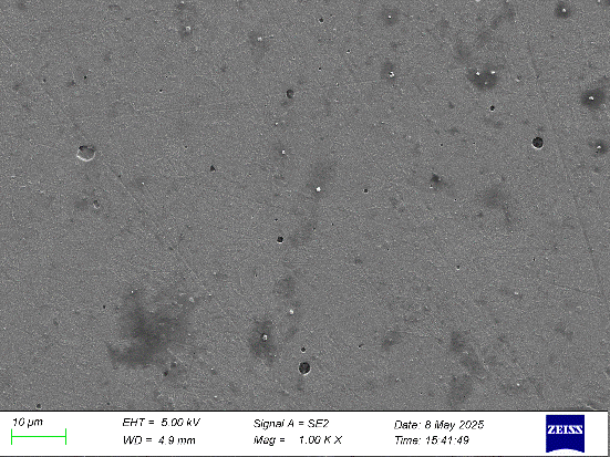
The surface morphology differences of TiN coatings prepared using straight tube filtering arc and unfiltered arc were compared, as shown in the figure, which intuitively demonstrates the significant advantages of straight tube filtering structure in suppressing particles. The TiN coating deposited using straight tube filter arc technology is shown on the left of the figure. The surface is overall smooth, with significantly reduced large particles and only a small amount of isolated small particles visible, indicating good surface quality of the coating. The coating prepared under traditional unfiltered arc conditions is shown on the right, with particles of different sizes distributed densely on the surface. The accumulation of a large number of particles not only reduces the surface density, but also may become the starting point for local failure of the film layer.
This difference is mainly due to the effective screening effect of the straight tube filtering arc structure. This technology uses a linear magnetic field channel to guide charged metal ions to the surface of the substrate, while non ionized liquid particles, due to their large mass and high momentum, cannot deviate their motion trajectory under the action of the magnetic field and are thus blocked outside the arc filter tube. Compared to the bent pipe structure, the straight pipe structure has a shorter transmission path and higher ion flux retention rate, which ensures sedimentation efficiency and effectively reduces particle pollution.
Therefore, the straight tube filter arc exhibits significant surface purification effects in TiN coating preparation, providing reliable technical support for obtaining dense, smooth, and mechanically sound film layers. This filtering mechanism is particularly suitable for the preparation of high-performance functional coatings with high requirements for surface roughness, friction performance, and corrosion resistance.
Telephone
Copyright @ 2026 Surfacility ICP:鲁ICP备2024132207号No:84506


Leave a Reply